Porous and Non Porous Transparent PEEK-WC Films
Academic Journal of Polymer Science - Juniper Publishers
Abstract
Membrane technology offers a wide range of applications and advantages in many fields. On the other hand, PEEK-WC is widely employed to produce membranes, also after chemical modifications, with different morphologies and different techniques, and for many applications. In this work transparent PEEK-WC membranes were produced, modifying just the preparation conditions. Transparent membranes find a lot of applications, from display protection film, in odontology, as impermeable pellicles, in cultural heritage protection, but also in traditional fields, as gas separation. Not all the membranes are transparent, but it seems clear that the oxygen presence during membrane formation is responsible of non transparence of the PEEK-WC membranes. Our membranes result optically transparent, also when their thickness is not so thin. By means of contact angle measurements, the membranes show a good resistance to sulfuric and nitric acid at low concentrations. Absorption coefficient measurements and SEM analysis were carried out in order to quantify the membranes transparence and the morphological modifications.
Keywords: Transparent Film; Membrane; PEEK-WC
Introduction
The research of new polymeric materials for membrane application is of great interest. Membrane technology offers a wide range of applications, but also a great number of advantages with respect to other traditional techniques. It is well known, however, that the properties of the membranes are widely influenced by their morphology and the choice of the polymer. In this work a particular kind of PEEK [1], named PEEK-WC (poly(oxa-p-phenylene-3,3-phthalido-p-phenylene-oxy-phenylene) [2], was used. The polymer is characterised by the presence of the cumbersome lattonic group that reduces the crystallinity degree thus making it more soluble in some chlorohydrocarbon solvents and also in DMF and DMSO. As a consequence, it is possible to obtain PEEK-WC membranes that are currently studied for many applications [3-5]. Various kind of PEEK-WC membranes were prepared in the past [6-14] and even today but none was found transparent until now. A good material is necessary to produce a high quality membrane, but the same material can allow to make membranes with different morphology and performance to be used in different field of application, depending on the particular preparation technique and the preparation conditions. Throughout in this work symmetric and asymmetric, porous and dense, transparent and opaque membranes were prepared. Usually during symmetric membrane preparation, the casted polymeric solution evaporates in air or in a coagulation bath, while during asymmetric membrane preparation the solution evaporates in air for few minutes and then is immersed in a non-solvent bath (Kesting, 1985). In this work, the difference with respect to traditional preparation conditions is the introduction of nitrogen in the environment of membrane formation and the presence of oxygen, from air or from water, that seems to be responsible of the opacity of the membranes. No flux and permeance results are reported because gas separation tests era in course.
Materials
PEEK-WC was supplied from Chanchung Institute of Applied Chemistry, Academia Sinica. The polymer powder was washed with methanol at room temperature and then dried in a vacuum oven before membrane preparation. N,N-Dimethylformamide (DMF) was supplied from Sigma Aldrich. The polymer solution was cast on a plate by means of a commercial knife Doctor Blade. Membrane thickness was measured by using Carl Mahr D 7300 Esslingen micrometer. Contact angle measurements were carried out on a Contact Angle Meter, CAM 100, a commercial device from KSV, Instruments Ltd. SEM imaging and analysis were made with a Feiquanta 200F. The adsorption coefficient of the films has been determined by means of an AvaSpec-2048 fiber optic spectrometer (Avantes).
Methods
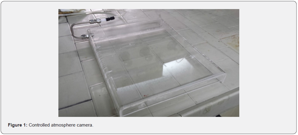
The solvent used to dissolve PEEK-WC was DMF and the non solvent, for asymmetric membranes, was water. The evaporation was carried out in air or in nitrogen. Nitrogen flowrate was controlled by using the apparatus showed in Figure 1, a controlled atmosphere camera, operating in steady state conditions. The nitrogen flowrate was of 400 mL/min, except for some cases in which it was enhanced, as specified. For all the membranes the purified polymer (20 wt%) was dissolved in DMF by magnetically stirring overnight to allow complete solution at room temperature. The solution was cast knife on a glass plate, with a gap of 500 mm. For each evaporation condition a different membrane was obtained, here indicated by uppercase letters, as reported in Tab. 1, which also summarises the preparation conditions. In order to evaluate the hydrophobicity of the membranes, contact angle to water was measured. When membranes are used in industrial applications, in a likely unlimited time, it is probable the presence of water, that makes the work environment potentially more aggressive due to the potential formation of some acids in the work environment. For this reason, measures of contact angle to sulfuric and nitric acid (10%) were carried out.
Results and Discussion
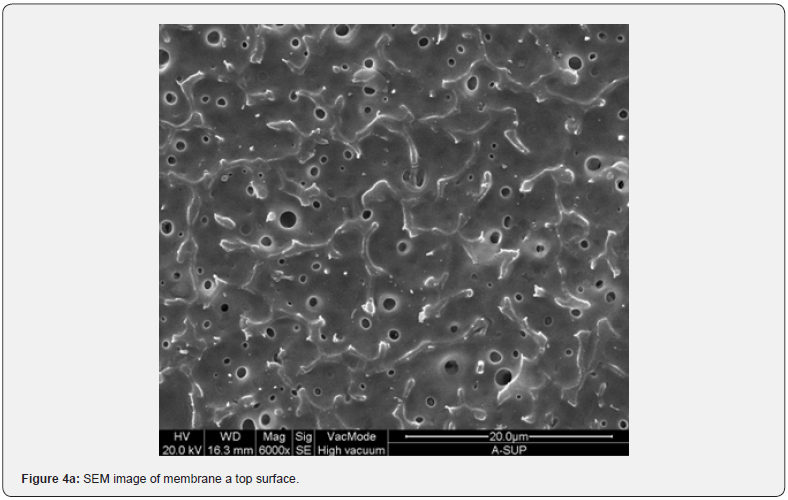
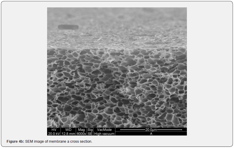
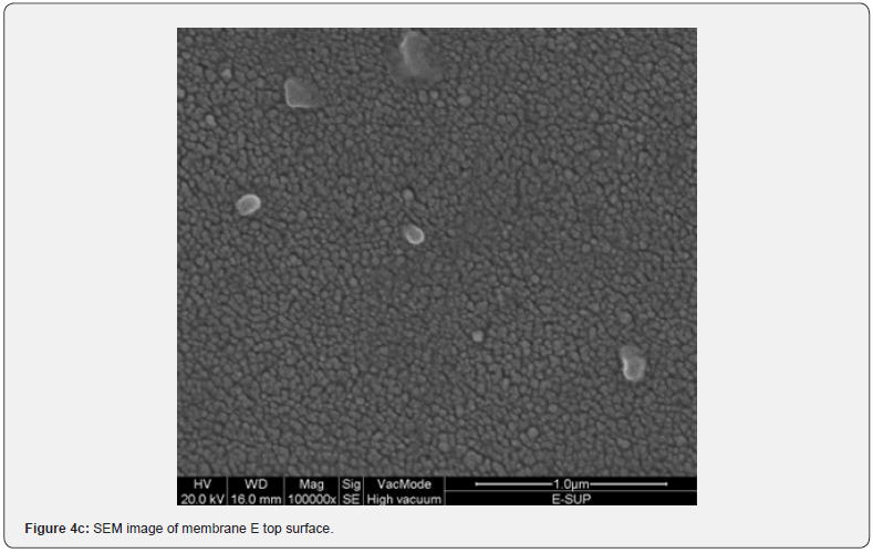
The formation of a membrane is widely influenced by the operating conditions. We included a nitrogen exposition of the polymeric film during its formation. This allows obtaining a transparent membrane, but not always. In relation to their appearance the membranes can be arranged in three categories: transparent (C,D,I,J,K,L), moderately transparent (G,H) and opaque (A,B,E,F,M,N,P). This optical feature is determined by both the surface topography and the bulk morphology of the films, that in turn depend from the particular preparation procedure. Scanning electron microscopy (SEM) images of both the surface and the bulk cross section of each membrane have been acquired. From a careful observation of these pictures we can draw the distinctive characteristics related to their optical features.
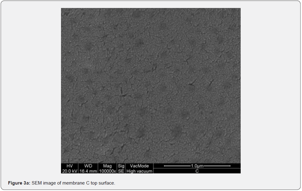
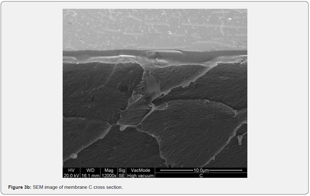
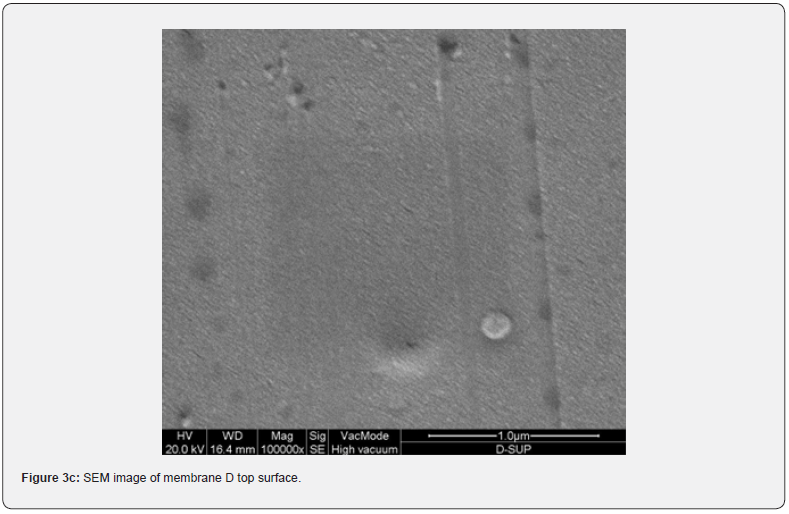
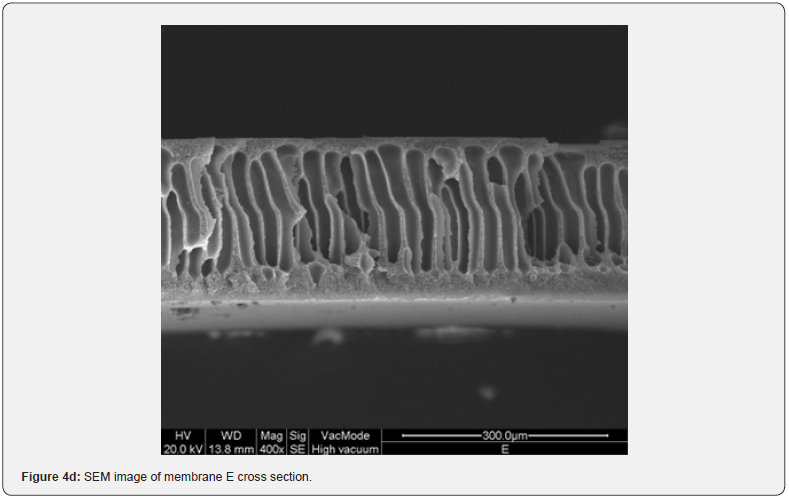
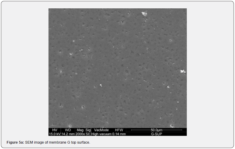
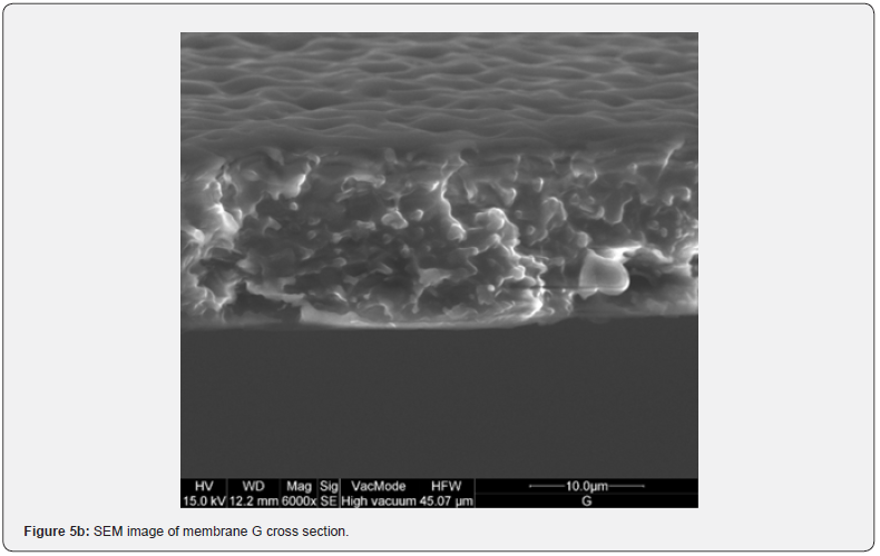
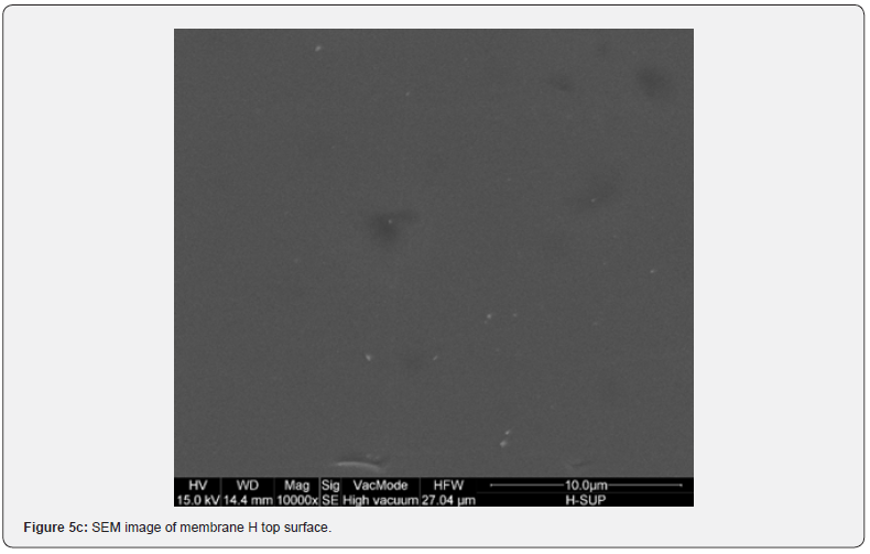
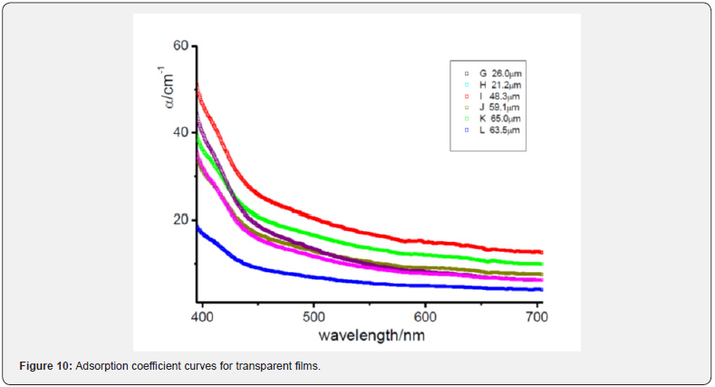
Figure 2 shows the absorption coefficient α=A/(n*d) of the membranes; where A is the absorbance, n is the refractive index (an average value 1.5 has been chosen), and d [cm] is the membrane thickness. In details, a transparent sample possesses a quite smooth surface and a uniform bulk (Figure 3, SEM membranes C and D). However, an opaque sample shows a surface with dips and bumps, and a spongy bulk whose typical pore size is lower than 2 mm, on average (Figure 4, SEM membranes A, E). The opacity of the latter kind of films is due to the strong light scattering caused either by the irregular surfaces and the cavity structure of the bulk. For this reason the absorbance of opaque samples cannot be measured owing to their strong diffusion. Two membranes are partially transparent, G and H (Figure 2), although for different reasons. In fact, sample G has a bumpy surface and a compact bulk (albeit apparently bulbous), while sample H has a smooth surface and a spongy bulk (Figure 5, SEM membranes G, H). Evidently, as the latter membranes have just one characteristic in common with the opaque one, they are partly transparent.
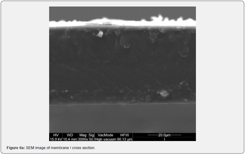
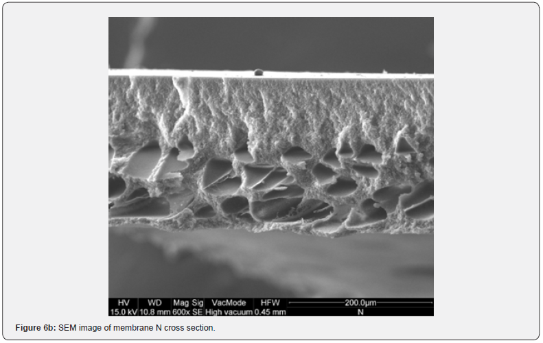
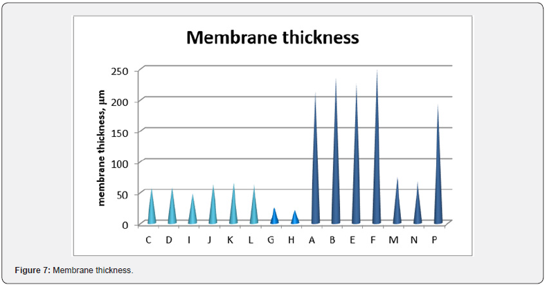
The resulting film morphology depends on preparation procedure and in particular on atmosphere and time of evaporation. In Figure 6 SEM images of the cross section of membranes I and N are showed. Even if H (Figure 5d), I and N membranes are, respectively moderately transparent, transparent and opaque, their top surface is completely homogeneous. The difference in their behaviour is in the cross section structures that are very assorted, because they are respectively homogeneously porous, symmetric dense and asymmetric, with a top layer, owing to nitrogen exposition, and a finger like structure, owing to water immersion (membrane N). The film thickness, reported in Figure 7, does not seem to affect the transparency. In fact, the thickness of transparent films is ranging between 57 and 71 mm, while G and H thickness is lower. Opaque membranes have higher thickness, except for M and N membranes, that show a similar thickness with respect to the transparent ones.



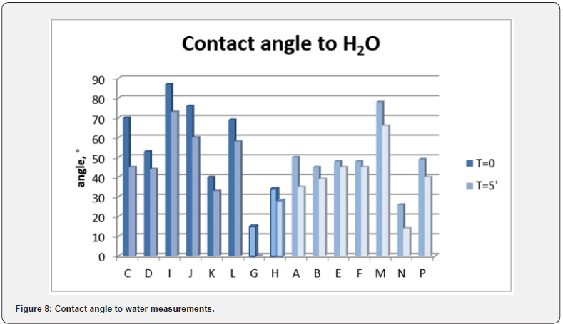
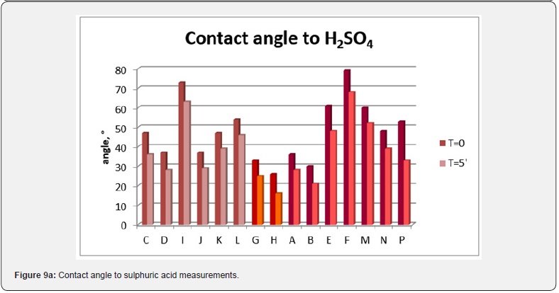
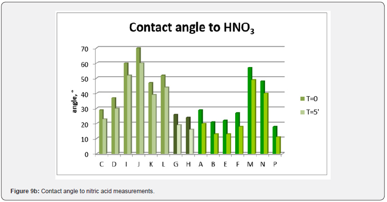
Contact angle measurements were carried out in order to evaluate the films hydrophobicity. The results are shown in Figure 8, where the measurements at zero time and after 5 minutes are reported. No particular difference can be noted among the films, all of them are in the range of hydrophilic membranes, even if the differences in the structure and in the roughness result in a different contact angle. In industrial applications, when the process is likely unlimited in the time, it is probable the presence of little amount of water. This means that the membranes are in a potentially more aggressive environment, for the possibility of the formation of some acids, helped by water. For this reason the choice of the membrane material and its intrinsic properties became very important. When in contact with acids, a membrane may be modified or damaged. In order to evaluate a first possible film modification, contact angle measurement to sulphuric and nitric acid (10%) were carried out (Figure 9). Considering a contact angle of 90° as a middle value, we can consider a resistant material the one with a contact angle upper to 90°. On the other hand, if the contact angle does not decrease shortly it is possible to suppose that no drastic modification occurs. It seems that transparent films are more resistant to acid with respect to the others, even if the contact angle values are similar to opaque membranes. On the contrary, the semitransparent films show the lower contact angle values, that means a greater affinity to acids.
Looking at the preparation conditions, it is clear that when nitrogen stream is absent or its exposition time is lower than 2 hours we obtain opaque membranes. On the other hand, for nitrogen exposition above 23 hours we obtain a transparent membrane. In the middle cases, when we have a membrane that is not optically transparent but not completely opaque yet, an intermediate time exposure to nitrogen occurred. In particular it seems that also the nitrogen flowrate plays its role. In fact, in Figure 2 absorption coefficient curves for the transparent films in the range of visible wavelength are approximately overlapped. If we look at them more carefully (Figure 10), it can be noticed that the most transparent membrane is the L one. This membrane was prepared by evaporating under a nitrogen flowrate of 800 ml/ min for 48 hours. These conditions are stronger with respect all the other films, because in this case we have the higher nitrogen flowrate and the longer evaporation time under controlled conditions.
Conclusion
Traditional PEEK-WC polymer was used to prepare transparent membranes, by changing evaporation atmosphere conditions. Summarizing, both topology and morphology of the membranes seem to depend on the preparation procedure. For the transparent ones, the preparation requires long time nitrogen exposure (>23h); for the opaque samples, on the contrary, the exposure time to nitrogen is quite short (<2h) or even absent; lastly, the semitransparent membranes were prepared with an intermediate time exposure to nitrogen.
For more Open Access Journals in Juniper Publishers please click on: https://juniperpublishers.com/
For more articles in Academic Journal of Polymer Science please click on: https://juniperpublishers.com/ajop/index.php


Comments
Post a Comment