A Comparative Study of Multiwalled Carbon Nanotube Based Polystyrene and Toughened Polycarbonate Nanocomposites-Juniper Publishers
Authored
by Nisha Bagotia
Abstract
The main objective of this article is to describe the
effect of different length (aspect ratio) of carbon nanotubes (CNTs) on
the electrical conductivity and electromagnetic shielding effectiveness
of polystyrene/l-MWCNT and toughened polycarbonate/s-MWCNT composites.
Long and short MWCNTs having aspect ratio of ~666 - 1333 and ~157
respectively were used for melt-mixed with polystyrene and toughened
polycarbonate in a micro compounder. The uniform dispersion of MWCNT in
matrix was confirmed by scanning electron microscopy. The realization
shielding effectiveness value of -21dB respectively for PS/l-MWCNT
composites: and -27dB for TPC/s-MWCNT composites at 10phr loading of
MWCNTs, which show their potential use in making of mechanically strong
and light weight EMI shield used for commercial application.
Keywords: Polycarbonate; Polystyrene; Multiwalled carbon nanotube; Electrical properties; EMI shielding effectiveness Abbrevations: Carbon Nanotubes; EC: Electrical Conductivity; EMI: Electromagnetic Interference; l-MWCNTs: Long Length Multiwalled Carbon Nanotubes; PC: Polycarbonate; PS: Polystyrene; PTT: Poly(trimethylene terephthalate); SE: Shielding Effectiveness; SEM: Scanning Electron Microscope; s-MWCNTs: Small Length multiwalled carbon nanotubes; s-MWCNTs: Small Multiwalled Carbon Nanotubes; SWCNTs: Single Walled Carbon Nanotubes; TEM: Transmission Electron Microscope; TPC: Toughened Polycarbonate; VNA: Vector Network Analyzer
Introduction
The broad developments of electronic systems and
telecommunications has led to a novel type of pollution i.e.
electromagnetic interference (EMI). EMI has appeared as a major problem,
which not only affecting the proper working of electronic devices but
as well as causing harmful effects to the health of human beings [1,2].
Generally, mobile phone, radar, radio transceivers, microwave oven, and
various electronic devices are the main causes of EMI [3,4]. The long
time exposure of EM waves have also been recognized as strong
cancer-causing agent [5]. Therefore, appropriate shield is required to
reduce the effect of EM waves. Generally, electrically conductive or
magnetic filler are used as a EMI shielding material, because these
materials have capability to interact with coupled electric and magnetic
fields of the incident EM waves [6,7]. Metals and metal loaded
composites have been widely used as EMI shielding materials, but these
materials have disadvantages such as high density, corrosion prone,
inconvenient processing etc. which limits their practical applicability.
As compare to the metals, carbon nanomaterials have appeared as
promising alternative conductive filler for production of EMI shield
[6,8,9].
Nowadays, the use of carbon nanotubes (CNTs), having
ultra-high modulus and strength, good thermal and electrical properties,
as filler in polymer nanocomposites prepare material with lower filler
loadings having improved electrical and EMI shielding properties
[10-15]. As reported in literature, mechanical strength, electrical
conductivity or thermal properties and EMI shielding effectiveness of
the polymer nanocomposites are affected by different factors such as the
aspect ratio, dispersion, processing methods, treatment methods, and
loading of CNTs [16]. Li et al. [15] studied the conductivity and EMI SE
of epoxy/SWCNT nanocomposites filled with SWCNTs having different
aspect ratios. The maximum EMI shielding effectiveness has been reported
for epoxy/SWCNT composites having 15wt% SWCNTs-long (SE ∼49dB and
15-20dB obtained at 10MHz and in the 500MHz to 1.5GHz range
respectively). In another study, Gupta et al. [17] reported EMI
shielding properties (in Ku-band) of poly (trimethylene terephthalate)
(PTT)/MWCNT nanocomposites. Electrical percolation of composites has
been reported at 1wt% loading of MWCNT and SE of 36-42dB reported at
10wt% loading of MWCNT. Bai et al. [18] described the effect of nanotube
aspect ratio on the electrical properties and mechanical strength of
the epoxy/MWCNT nanocomposites using three different length of
MWCNTs (~1,10,50μm). It has been found that the short length
MWCNTs (10μm) report good mechanical properties while
long length MWCNTs (50μm) improved electrical properties of
nanocomposites. Singh et al. [19] investigated the effect of CNTs
having different aspect ratio on the electrical, mechanical and
EMI shielding properties of epoxy/CNTs nanocomposites at
low loading of CNT (0.5wt%). It has been observed that high
aspect ratio CNTs filled nanocomposites show higher electrical
(percolation threshold at 0.02wt% loading of l-MWCNT),
mechanical (125MPa at 0.3wt% loading of l-MWCNT) and EMI
shielding properties (highest SE ~16dB) in comparison to those
filled with lower aspect ratio MWCNTs (percolation threshold at
0.11wt%, flexural strength -113MPa at 0.3wt% and maximum
shielding of ~11dB). Huang et al. [20] investigated the effect
of heat treatment and CNTs with different aspect ratio on the
EMI shielding effectiveness of epoxy/SWCNT nanocomposites
(up to 15wt% SWCNTs). They reported that long SWCNTs based
nanocomposites give high EMI SE (SE ~3 to 28dB) as compared
to short annealed SWCNTs (SE ~21-23dB) and unannealed
short SWCNTs (SE ~17-18dB). Al-Guo et al. [21] studied the
effects of MWCNTs with high aspect ratio (313 and 474) on the
electrical, mechanical, and thermal properties of PC/MWCNT
nanocomposites. Above mentioned literature showed that most
of studies either show EMI shielding effectiveness or mechanical
properties of different types of MWCNTs based nanocomposites
under higher loading of CNTs; or with both mechanical and
EMI properties under lower loading of CNTs. Therefore, a
comparative study of the preparation of higher loaded MWCNT
nanocomposites and describing the effect of aspect ratio of
MWCNTs on the mechanical, electrical and EMI shielding
properties, of polymer nanocomposites is necessary.
The main objective of this paper to describe the effect of
aspect ratio of MWCNTs on the electrical and EMI shielding
properties of MWCNT based polystyrene (PS) and toughened
polycarbonate (TPC) composites containing up to 10phr
MWCNTs. The nanocomposites have been prepared by melt
compounding of PS and TPC with MWCNTs in a twin screw
micro-compounder. Two types of MWCNTs viz. long (l-MWCNT)
having diameter ~7.5nm & length ~5-10μm (aspect ratio ~666-
1333) and short (s-MWCNTs) having diameter 9.5nm & length
~1.5μm (aspect ratio ~157) were used for the fabrication
of nanocomposites. The dispersion of MWCNTs in matrix is
investigated by scanning electron microscopy. The EMI shielding
of nanocomposites was measured in X-band (frequency range of
8.2-12.4GHz). The morphology, electrical conductivity and EMI
shielding effectiveness of composites have been interrelated
with distribution density and aspect ratio of CNTs, under both
lower and higher loading.
Materials and Methods
Materials
Polystyrene (SC206) was purchased from Supreme
Petrochem limited. Polycarbonate (PC) Lexan 143, procured
from Sabic Innovative Plastic. Ethylene methyl acrylate (EMA)
copolymer (Elvaloy® AC 1330 from DuPont) having 70% by
weight ethylene and 30% by weight methyl acrylate are used in
this investigation for toughening of PC [22,23]. Here, 5wt% EMA
containing PC (TPC) is used for study. The long length MWCNTs
(l-MWCNTs) were produced by CVD method using pongamia oil
as a carbon source and ferrocene as catalyst and preparation
process is mentioned elsewhere [24]. The diameter of l-MWCNT was in the range of 50-200nm and length is in the range 5-10μm.
The short length MWCNTs (s-MWCNTs), grade NC7000 with
90% carbon purity (length ~1.5μm and diameter ~9.5nm) were
obtained from Nanocyl, Belgium.

Methods
Fabrication of PS/MWCNT and TPC/MWCNT nanocomposites
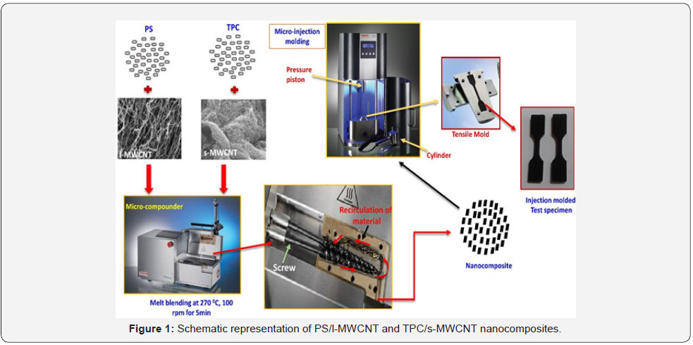
The melt blending approach for fabrication of PS/l-MWCNT
and TPC/s-MWCNT composites was used in this study. Drying
of PS, TPC and MWCNTs was performed before melt blending
for 24 h at 70 °C in oven. Melt blending of nanocomposites was
carried out by using micro-compounder at 270 °C processing
temperature, screw speed 100rpm and mixing time 5min. The
continuous strands obtained were pelletized and then followed
by drying in the oven for injection molding. The micro-injection
molding machine was used for the preparation of test specimen
of PS/l-MWCNT and TPC/s-MWCNT nanocomposites. Cylinder
temperature, mold temperature and pressure for injection
molding were 250 °C, 100 °C and 640bar respectively. The
formulation and sample designation of the PS/l-MWCNT and
TPC/s-MWCNT composites are given in Table 1. The schematic
representation of the nanocomposites fabrication is illustrated
in Figure 1.

*where PS-polystyrene, TPC- toughened polycarbonate,
l-CNT- long multiwalled carbon nanotube, s-CNT- small
multiwalled carbon nanotube, Numerical value- MWCNT
content.
Characterization of PS/MWCNT and TPC/MWCNT
nanocomposites
PS and TPC nanocomposites were characterized by
morphological, electrical, EMI shielding thermal and
spectroscopy study. Surface morphology of these nanocomposites
were inspected using scanning electron microscope (SEM Zeiss
EVO 50 at magnification of 30,000) and transmission electron
microscope (TEM Zeiss 200kV). The cryofractured surface
of composites were used for SEM imaging. The electrical
conductivity (EC) of the nanocomposites at room temperature
was measured by two point contact method using a Keithley 224
programmable current source. Electromagnetic interference
shielding of composites were recorded on Agilent E8362B
Vector Network Analyzer (VNA) in 8.2-12.4GHz frequency range
(X-band).
Results and Discussion
Morphological characterization
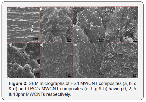
SEM images of l-MWCNTs and s-MWCNT based PS and TPU
nanocomposites are presented in Figure 2a - 2h respectively.
MWCNTs are homogenously dispersed in the matrix, even
at 10phr loading as observed from the images. Thus, melt
blending using micro-compounder is an effective technique
for homogenous dispersion of MWCNTs in matrix. From SEM
images, it is also observed that, at any specific MWCNT loading,
the distribution density of s-MWCNT in TPC matrix is higher
compared to l-MWCNTs in PS matrix. These s-MWCNTs have
more surface area in comparison to l-MWCNTs for interfacial
interactions with TPC matrix, which are necessary for good
mechanical strength and EMI shielding. On other side, l-MWCNTs
with higher aspect ratio are expected to provide good stress
transfer properties, low percolation threshold and long-range charge transport in PS matrix. Therefore, depending on the
aspect ratio of MWCNTs, their distribution and loading inside
matrix, significant mechanical, electrical and EMI shielding
properties are expected.

Electrical conductivity (EC)
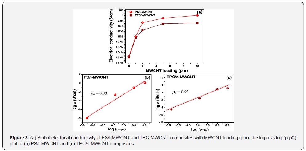
The EC of PS/l-MWCNT and TPC/s-MWCNT nanocomposites
with respect to MWCNT loading is presented in Figure 3. The
EC of nanocomposites based on l- and s-MWCNT increased with
increasing MWCNT loading and shows a drastic increase (~
eight and seven orders of magnitude respectively) below 1phr
MWCNT content, which show the formation of 3D conducting
networks. Such a low percolation threshold value is due to
the uniform dispersion of MWCNTs in matrix. It is reported in
literature that percolation threshold is basically dependent on
the different factors like the aspect ratio, intrinsic conductivity
and dispersion of the conductive nanofiller [25-27]. Therefore,
the exact value of threshold of l- and s-MWCNTs, has been
projected by plotting the EC as a function of the MWCNT loading
and performing data fitting using the scaling law [28-


where σ , σ 0 , ρ , ρ 0 and t represents the EC of the
nanocomposites the intrinsic conductivity of the nanofiller,
volume fraction of nanofiller, the volume fraction at the
percolation threshold and the critical exponent related to the
system dimensionality respectively.
The linear regression data fitting (Figure 4 b & 4c) gives ρ0 =
0.83phr & β = 1.54 for PS/l-MWCNT and ρ0 = 1.07 wt.% & β = 1.09 for TPC/s-MWCNT nanocomposites.
Considering the good dispersion of both l- and s- MWCNTs, the low
percolation threshold for l-MWCNTs can be attributed to its high
aspect ratio as compared to s-MWCNTs. It can also be seen that
at any loading level, EC of PS/l-MWCNT nanocomposite is higher
than respective TPC/s-MWCNT nanocomposite. This can again
be attributed to the higher aspect ratio of l-MCWNTs responsible
for long range charge transport in nanocomposites. As the EMI
shielding is also related to the EC, the observed EC trend of
nanocomposites recommend that, at comparative loading, EMI
shielding effectiveness of PS/l-MWCNT nanocomposites should
be higher than TPC/s-MWCNT nanocomposites.
Electromagnetic interference shielding (EMI SE) of nanocomposites
The EMI SE is the capacity of a material to attenuate incident
electromagnetic waves. The EMI shielding is a direct result of
the absorption of the wave as it passes through the shield’s
thickness, the reflection of the wave from the front face of
the shield and multiple reflections of the waves at various
interfaces. The presence of charge carriers in material helps
in electromagnetic wave reflection via reflection mechanism
electromagnetic wave penetrate through the material and
get attenuated via the absorption. Absorption loss is more
important for the magnetic field of electromagnetic wave than
the electric field. Therefore, the electric field of electromagnetic
wave is mostly reflected at the interface. The total SE of a
material can be expressed in logarithmic power ratio as [32]

Where SEA, SER and SEM are the SE due to absorption,
reflection and multiple reflections respectively and Pi is the
power of incident wave and Pt is transmitted EM wave.
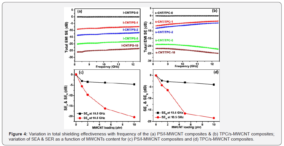
Figure 4a & 4b shows the total SE of PS/l-MWCNT and TPC/
s-MWCNT nanocomposites respectively. It can be observed that
neat matrix (PS and TPC) sample gives negligible attenuation.
However, incorporation of MWCNTs causes enhancement in
SE for both PS/l-MWCNT and TPC/s-MWCNT nanocomposites
obtaining SE value of - 21dB and - 27dB at 10phr loading
of MWCNT, respectively as given in Table 2 & 3. This can be
ascribed to the formation of conducting networks throughout
the insulating PS and TPC matrix. The EMI shielding results also
shown that at lower loading (up to 2phr MWCNT loading), SE of
PS/l-MWCNT nanocomposites is higher compared to s-MWCNT
based nanocomposites, but at higher loadings, s-MWCNT based
composites show higher EMI SE. Accordingly, PS/l-MWCNT-1
and TPC/s-MWCNT-2 show approximate similar shielding
effectiveness (~-7.8db). These results indicate the effectiveness
of l-MWCNTs at lower loading and s-MWCNTs at higher loading.


The total SE have two components i.e. reflection and
absorption (SER and SEA). Both SER and SEA increases with
MWCNT loading can be observed from Figure 4c & 4d. The SEA
increases at much faster rate as compare to SER in both the cases
with increase in MWCNT loading. A brief investigation shows
that at any given loading l-MWCNTs filled nanocomposites
show superior SER value as compare to s-MWCNTs filled
nanocomposites. However, absorption trend shown that below
5phr loading of CNT, PS/l-MWCNT nanocomposites show
superior SEA values whereas at higher loadings, SEA of TPC/s MWCNT nanocomposites dominate. This can be attributed to the
fact that at lower loadings, the interfacial polarization effects are
not too dominant, and conductivity shows the important role.
Consequently, the TPC/s-MWCNT nanocomposites with a lower
conductivity compare to PS/l-MWCNT nanocomposites show
lesser attenuation. However, at higher loadings, better input
impedance matching in case of TPC/s-MWCNT nanocomposites
allows more incident waves to enter inside the shield that can be
effectively dominated by absorption mechanism.
Conclusion
PS/MWCNT and TPC/MWCNT nanocomposites having up to
10phr loading of different aspect ratio MWCNTs (i.e. long and
short MWCNTs respectively) have been prepared by melt mixing
method. These nanocomposites show improved electrical
conductivity and low electrical percolation threshold (i.e. 0.83
and 0.91phr for PS/l-MWCNT and TPC/s-MWCNT composites
respectively) which is the sign of uniform dispersion of
MWCNTs in the matrix. Further, the good electrical conductivity,
processing induced morphology and difference in aspect ratio
are responsible for observed maximum attenuation of -21dB and
-27dB for PS/l- MWCNT and TPC/s-MWCNT nanocomposites
respectively. It was also detected that PS/l-MWCNT
nanocomposites show better SE at lower loading (up to 5phr)
whereas TPC/s-MWCNT nanocomposites give better SE at higher
loading. The aspect ratio of MWCNTs have been interconnected
with the observed trends of electrical conductivity and EMI SE.
These nanocomposites with good electrical conductivity along
with high EMI shielding are considered as potential aspirant for
making commercially feasible EMI shields.
For more
details Academic
Journal of Polymer Science please click on: https://juniperpublishers.com/ajop/index.php
To read more…Full Text in Juniper Publishers click on https://juniperpublishers.com/ajop/AJOP.MS.ID.555561.php

Comments
Post a Comment