Analysis of Non-Uniform Expansion Behavior of Injected EVA-Juniper Publishers
JUNIPER PUBLISHERS- Academic Journal of Polymer
Science
Abstract
Currently the sports footwear market is very
competitive, in which it is sought to produce products that provide high
performance, using technology in the production processes as well as in
the materials used. One of the main materials used in the composition
of soles and midsole of these products is EVA (Ethylene-Vinyl Acetate),
which brings several benefits such as cost reduction, comfort, lightness
and softness. The injection molding process is the most efficient for
obtaining EVA soles, however, EVA undergoes large expansions that may
vary according to its formulation and geometry of the desired model. The
objective of this work is to analyze the non-uniform deformation of
EVA, used in the injection molding processes, as well as one method used
to correct such distortions that occur in the expansion of this
material. For this, a bibliographic review was carried out to analyze
the chemical composition of the EVA, whose composition will determine
the characteristics of expansion and softness. The work also addresses
the steps of the injection process by analyzing the temperatures and
pressure employed and an analysis of how to predict and correct the
distortion in EVA expansion. It is proposed to use a section of a 3D
model, where it is determined where compensations should be applied and
using 3D modeling software.
To analyze the generation of smaller bubbles in less
thick regions of an EVA sole, a scanning electron microscope (SEM)
analysis was performed. In addition, the measurements of the analyzed
model were compared with the virtual model through a 3D scan. Hardness
tests on the Asker C scale and injection simulations were also performed
to analyze the cooling time of the part after leaving the mold,
volumetric contraction that occurs in the extraction of the mold part,
and the thicknesses of the walls of the product. The results indicate
that the comparison of the models was within the accepted tolerance,
which allows a variation in the expansion of up to 1mm in the length of
the evaluated points. From the analyzes made in the scanning electron
microscope and in the hardness test, it was possible to verify that in
regions of smaller thickness and smaller volume, the EVA blend cannot
have its total expansion, i.e., micro bubbles of gases generated in the
expansion are smaller in these regions when compared to regions of
greater volume and thickness. Consequently, these regions become denser
and less soft. Simulations indicated that in regions where bubbles do
not expand, there is also an early cooling of the material when compared
to regions with higher volume, proving that the cooling time is
directly linked to the EVA expansion rate.
Keywords: EVA; IMEVA; Expansion; Midsole; Sole; Shoe; Footwear; Mold design; Mold injectionAbbrevations: EVA: Ethylene-Vinyl Acetate; SEM: Scanning Electron Microscope
Introduction
With increasing global competitiveness, the search
for new materials that provide higher-quality, better-designed products
that increase production efficiency are critical for companies that want
to stay competitive. Many manufacturers of sports shoes have adopted
EVA injected as the main component in soles and midsole, as this
material allows to make light, soft and cheap sneakers. However, the EVA
requires some care and some procedures must be adopted to obtain
injected parts of good quality. EVA has the capacity to expand from 30%
to 90% its size and there is great difficulty in predicting how this
expansion occurs due to non-uniformity in the expansion process.
This article analyzes the non-uniform behavior of EVA
expansion and some methods used to correct this deformation.
Through years of experience and with the aid of 3D modeling
software, compensations are applied at certain points of the product,
according to the geometry, to try to predict the behavior of the
material. In order to obtain the EVA (Ethylene-Vinyl Acetate) that is
molded in the injection process, it is necessary to make a mixture to
acquire a compound that will determine the characteristics of expansion
and softness of the material, for the formulation of the compound we can
have the following types of raw materials [1]:
a. Resins: It is the base of the blend. Generally,
the EVA resin is mixed with LDPE and elastomers depending on the
desirable properties;
b. Expanders: These are organic or inorganic compounds that, by the action of heat, decompose to generate solid and
gaseous byproducts of diverse nature, thus being responsible
for the expansion process;
c. Activators: They are catalysts, decrease the decomposition
temperature of the blowing agent, thus avoiding the
degradation of the polymer matrix;
d. Cross-linking agents: They are responsible for forming
crosslinks in the polymer, increasing dimensional stability,
chemical resistance, heat stability, and stiffness of the
compound;
e. Lubricants: They are substances that decrease the friction
between the polymer chains facilitating the processing and
decreasing any interaction of the polymer mass with the
equipment used;
f. Plasticizers: These are liquid substances with high boiling
points and low molecular weight. When added to a polymer,
they increase the flexibility and softness of the product. In
the processing of EVA foams the aromatic plasticizers are the
most used;
g. Pigments: Organic and inorganic compounds responsible
for coloring the foams, influence the expansion of the
material. In EVA you can pigment with different colors.
h. Loads: These are insoluble solids which are added to
the polymers during processing in amounts sufficient to
decrease the final cost or to change some of their physical
properties in a controlled manner.
Eva Injection Molding Process
After blending to form the EVA compound for injection
is completed, the material is taken to an injector that can be
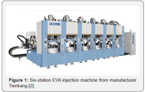
rotating or with stations aligned according to Figure 1. The
justification for adopting a machine with many stations is given
by the fact of the average injection cycle of each mold is high,
around 7 minutes, so with a multi-station machine you can
achieve a faster and more efficient production.
Below the steps of the injection process [3]:
(a) The mixture is added to the injector storage tank.
(b) The injection volume is calculated and adjusted according
to the mold.
(c) The material is heated to 95 °C and injected into the mold
at a pressure of ~1200bar.
(d) The mold is heated to 170 °C to activate the expander and
also the crosslinking agents
(e) The mold is kept closed at 170 °C until the crosslinks are
fully completed, about 1.5min / mm thick
(f) The mold is opened, and the EVA sole jumps out of the
cavity rapidly and begins to expand.
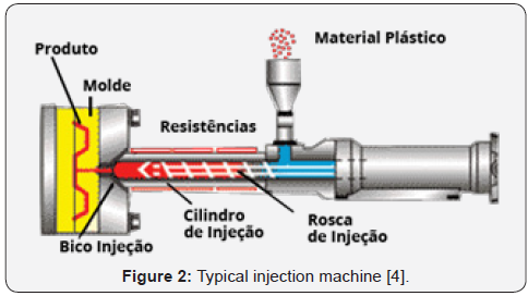
Injection in a typical injection machine can be observed in
Figure 2. In order to obtain an EVA midsole or midsole injected
into the appropriate dimensions, we must follow a few steps,
where through experience in this type of product, we know in
which points we should apply the compensations to correct the
subsequent distortion in the EVA expansion.
First, we must have our 3D model defined, from there we
follow the next steps:

• To demonstrate the steps, we will use a section of an
example 3D model, as in Figure 3.
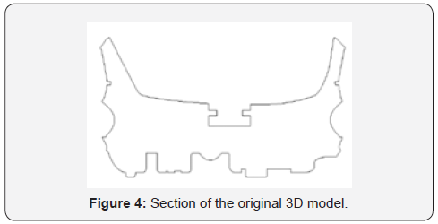
• The 3D modeling software called Rhinoceros [5],
geometry deformation tools were used to compensate for the
points of interest (Figure 4 &5).
After the compensations, the general expansion factor was
applied, which is reprinted in Figure 6 by the blue line, which
can vary from 30% to 90%, depending on the formulation of the
EVA blend, this factor was applied reducing the size of the model.
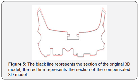
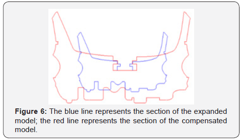
After the compensions o and the general expansion factor
were applied, as it was a model for aluminum casting, a further
1.2% was also applied to compensate the contraction of the
aluminum. If it were a completely milled mold, there was no
need to compensate for the shrinkage of the aluminum.
Analysis and Results
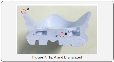
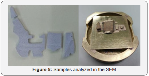
To verify the generation of smaller bubbles in less thick
regions, a cross section was cut from an eva sole, so an analysis
can be performed in the electron scanning microscope (SEM) of
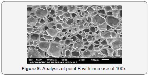
Feevale University, comparing images at points A and B (Figure
7&8) of the same product, with increases of 50x and 100x. Figure
9 shows the analysis at point B, made in SEM with a 100-fold
increase, we can clearly observe the formation of larger bubbles
when compared to Figure 10, which represents point A and this
with the same increase of 100times.

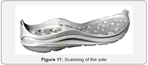
To verify if the analyzed model reached the desired
measurements, the original virtual model was compared with a
3D scanning, this was done in a 3D scanner, model Infinite 2.0, of
the manufacturer Cimcore (Figure 11&12) [6].
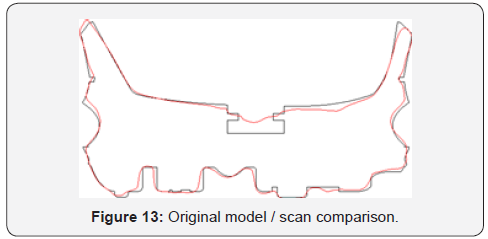
The result of the comparison of the models was within the
accepted tolerance, which allows a variation in the expansion
of up to 1mm in the length of the points in question. This comparison can be seen in Figure 13, where the black line
represents the original 3D mole and the red line represents a
scan of the injected EVA sole.

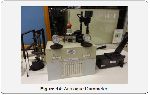
Also, for points A and B were made hardness tests using
the Asker C (A/C) scale, with an analogue durometer and 5mm
spherical tip (Figure 14). For comparison purposes, the two
samples were prepared with 3mm thickness and an average of
3 results were made. The average hardness found at point A was
58 A/C and at point B was 44 A/C
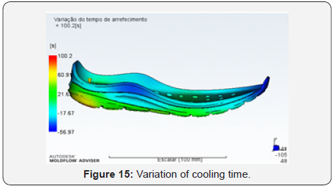
Injection simulations were performed in Autodesk Moldflow
Adviser software [7], where it was possible to perform several
analyzes, such as:
a. Variation of the cooling time of the part after leaving
the mold, Figure 15.
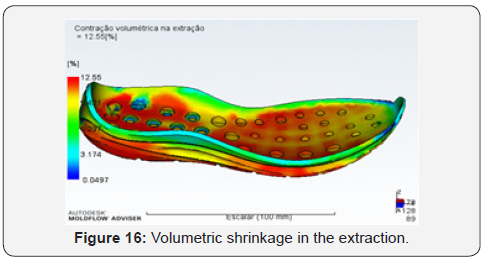
b. Volumetric contraction occurring in the extraction of
the mold part, Figure 16.
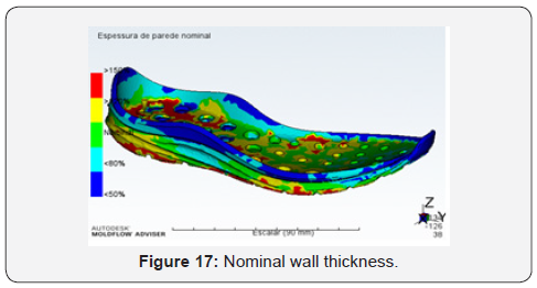
c. Thickness of the product walls, Figure 17.
Final Considerations
From the analyzes made in the scanning electron microscope
and in the hardness test, it was possible to prove that in regions
of smaller thickness and lower volume the EVA blender expander
cannot have its total expansion, that is, the micro bubbles of
gases generated at the moment of expansion are smaller in these
regions when compared with regions of greater volume and
thickness, consequently these regions become denser and less
tender. This directly influences the final geometry of the product Figure 18. The compensation methods to correct the distortion
of the EVA parts work satisfactorily within the tolerance,
however they cannot predict all cases of distortions, since the
models generally present varied and complex forms. Simulations
done in Autodesk Moldflow Adviser [7], demonstrated that in
these regions where the bubbles do not expand, there is also
an early cooling of the material, when compared to regions of
higher volume, thus proving that the cooling time of the material
is directly linked to the EVA expansion rate.


Comments
Post a Comment